February 2024
28th February 2024
2024 did not start that well, it started off with me being ill, what started off a cold quickly developed into a chest infection which took two courses of antibiotics and steroids before it finally cleared up.
This meant that virtually no progress was made at all on the model during January although I did spend a little time on the PC doing some more work on the design, specifically working on the wheel arches / fenders which I continued to refine during February.
This like the rest of the 3D design was done by translating 2D drawings into a usable 3D designs.
2D design is initially produced in Microsoft Visio so that accurate measurements can be taken at predefined intervals. This is done for both plan and elevation to create a 3D model of each point along the line of the fenders.
Below are the plan and elevation drawings for the rear fender.
Plan
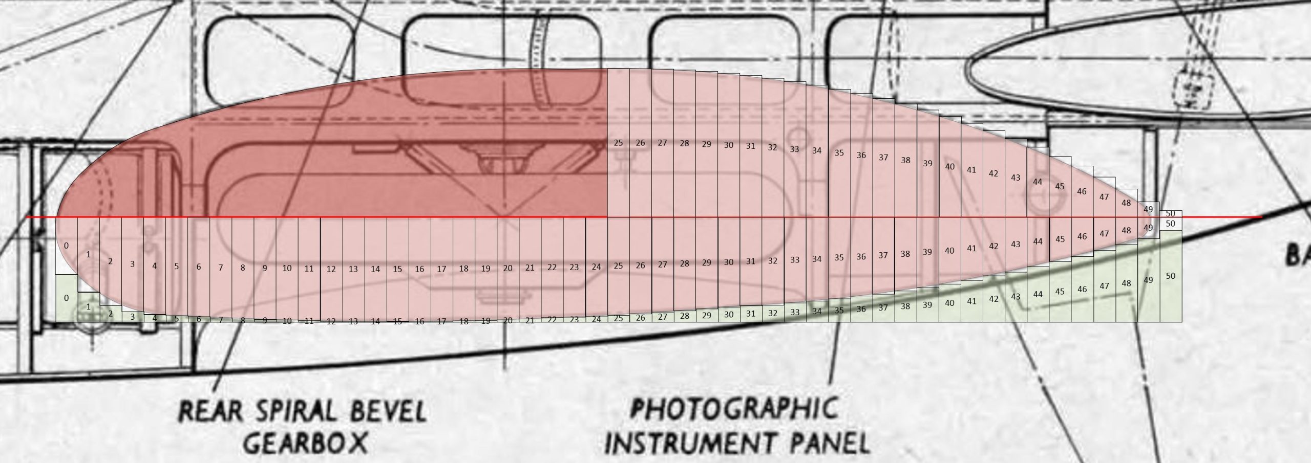
Elevation
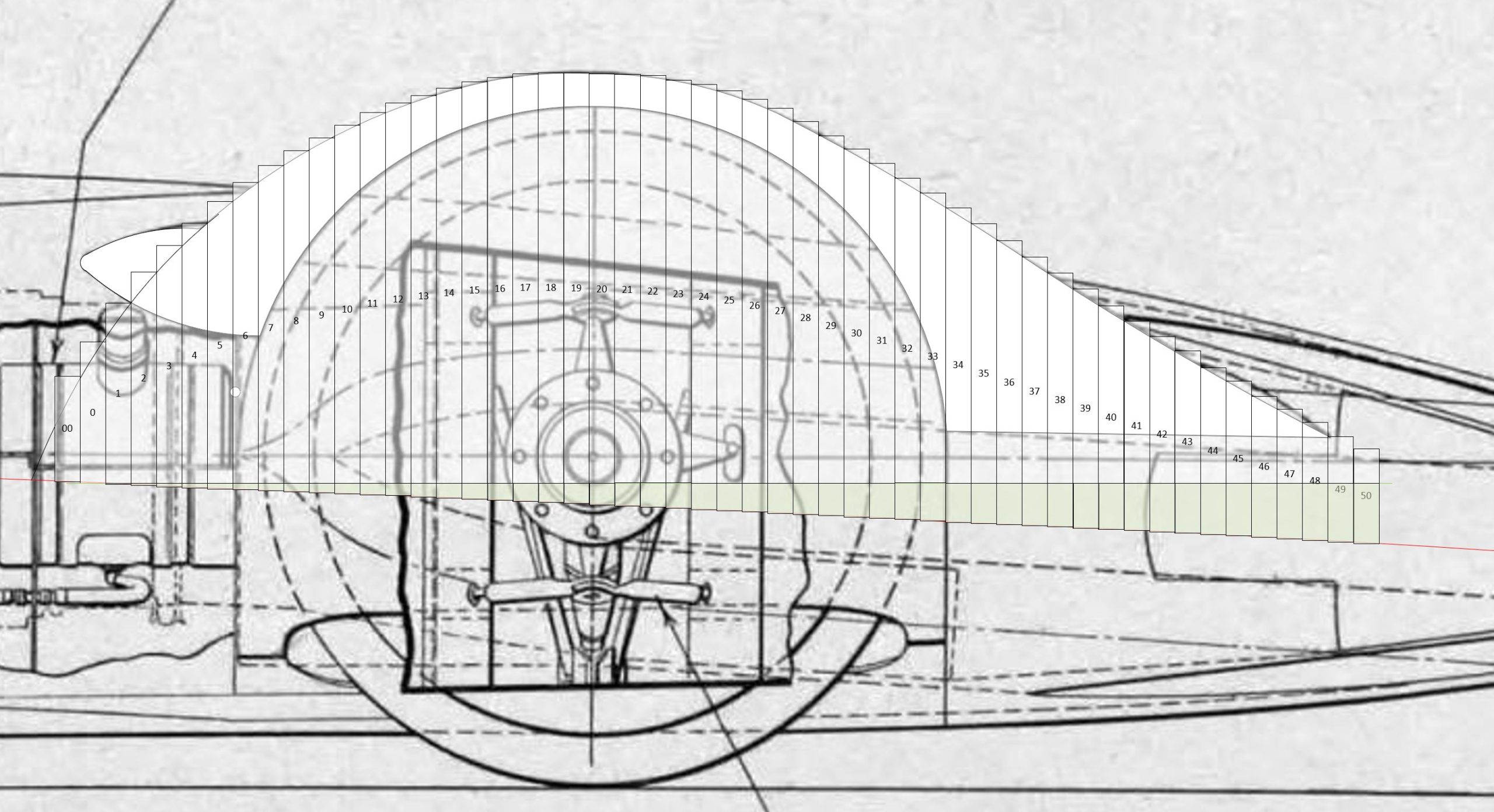
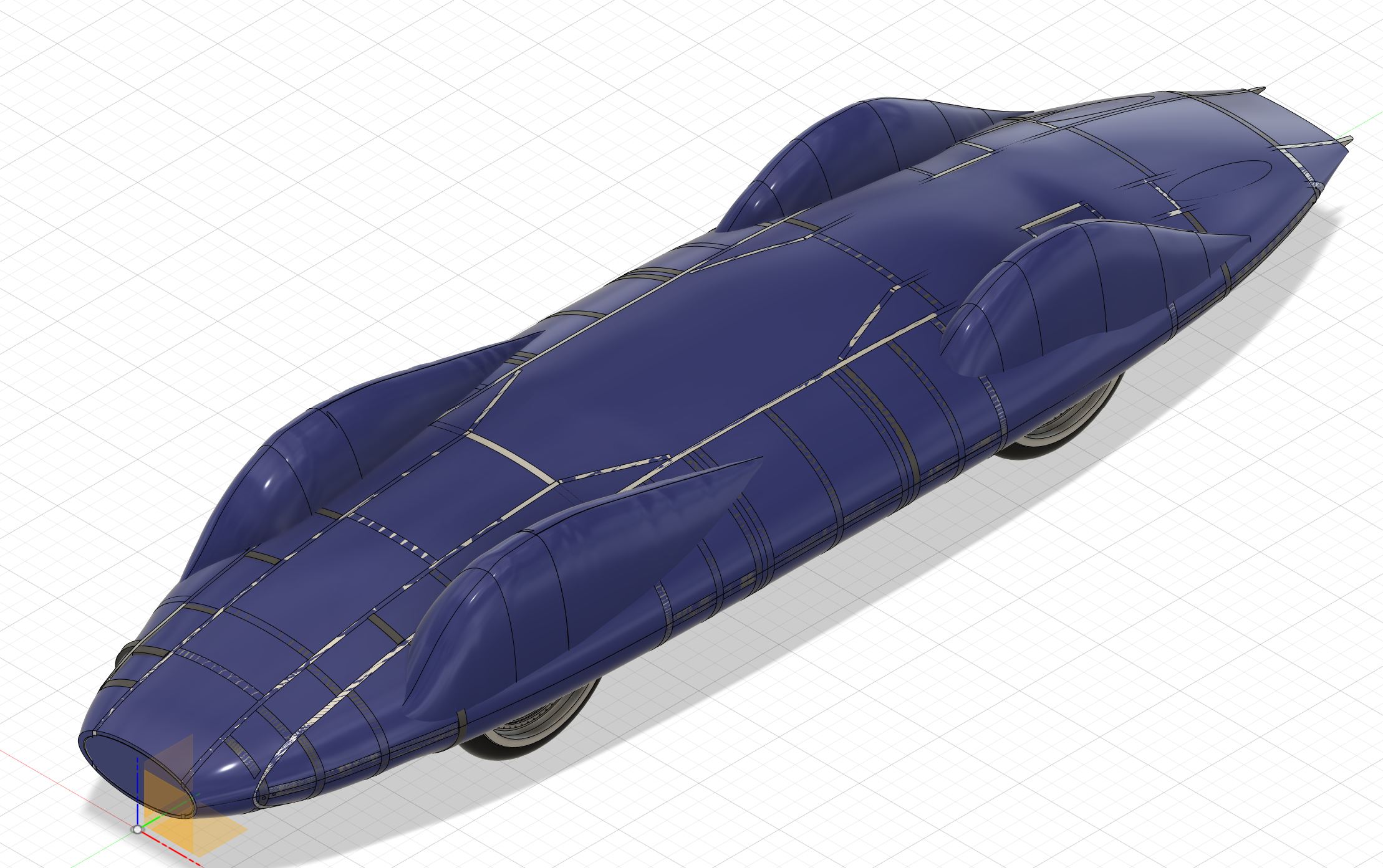
Each of these measurements is then translated to a 2D profile of the fender at intervals and with a specific offset from the predefined baseline. Each of these 2D shapes are then combined to create a 3D rendering in AutoCAD Fusion 360 of the fender which is relatively accurate to the original drawing. Although 100% accuracy is simply not possible using this method as part of the profile creation is simply based on what looks right.
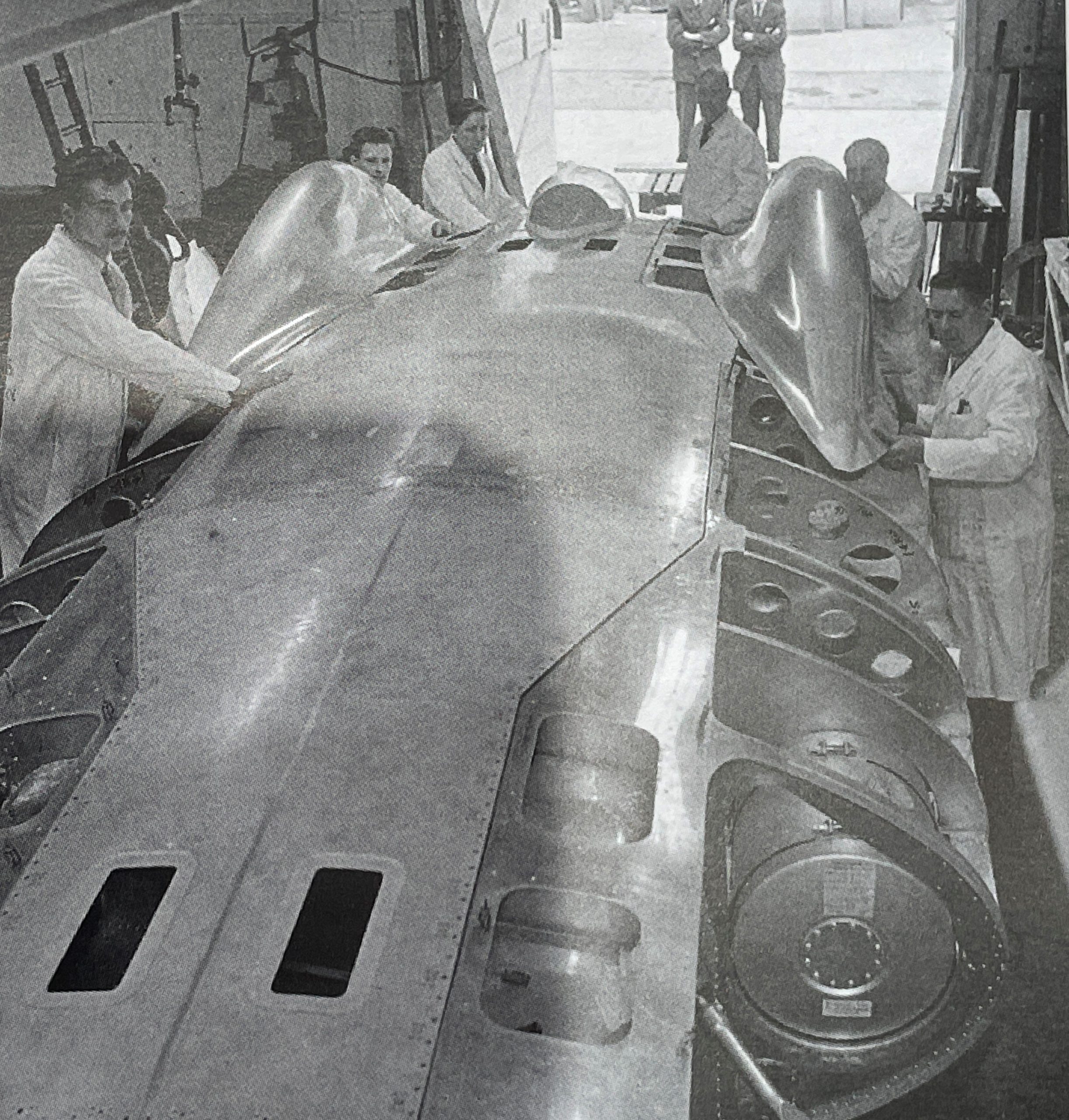
All body panels will be formed from aluminium sheet, which will need to be shaped and bent to the correct profile. This will need to done for all body panels including the wheel fenders. Bucks will be 3D printed for each of the fenders. Bucks are used in many industries and are tooling which help create complex shapes in a variety of materials. In the classic automotive industry, they are used to help a metalworker to create the bodywork for vehicle. The buck is a point of reference to help guide the metalworker when creating body panels.
My assumption is that Motor Panels LTD of Coventry used backs in forming many of the body panels for Bluebird CN7 especially the fenders.
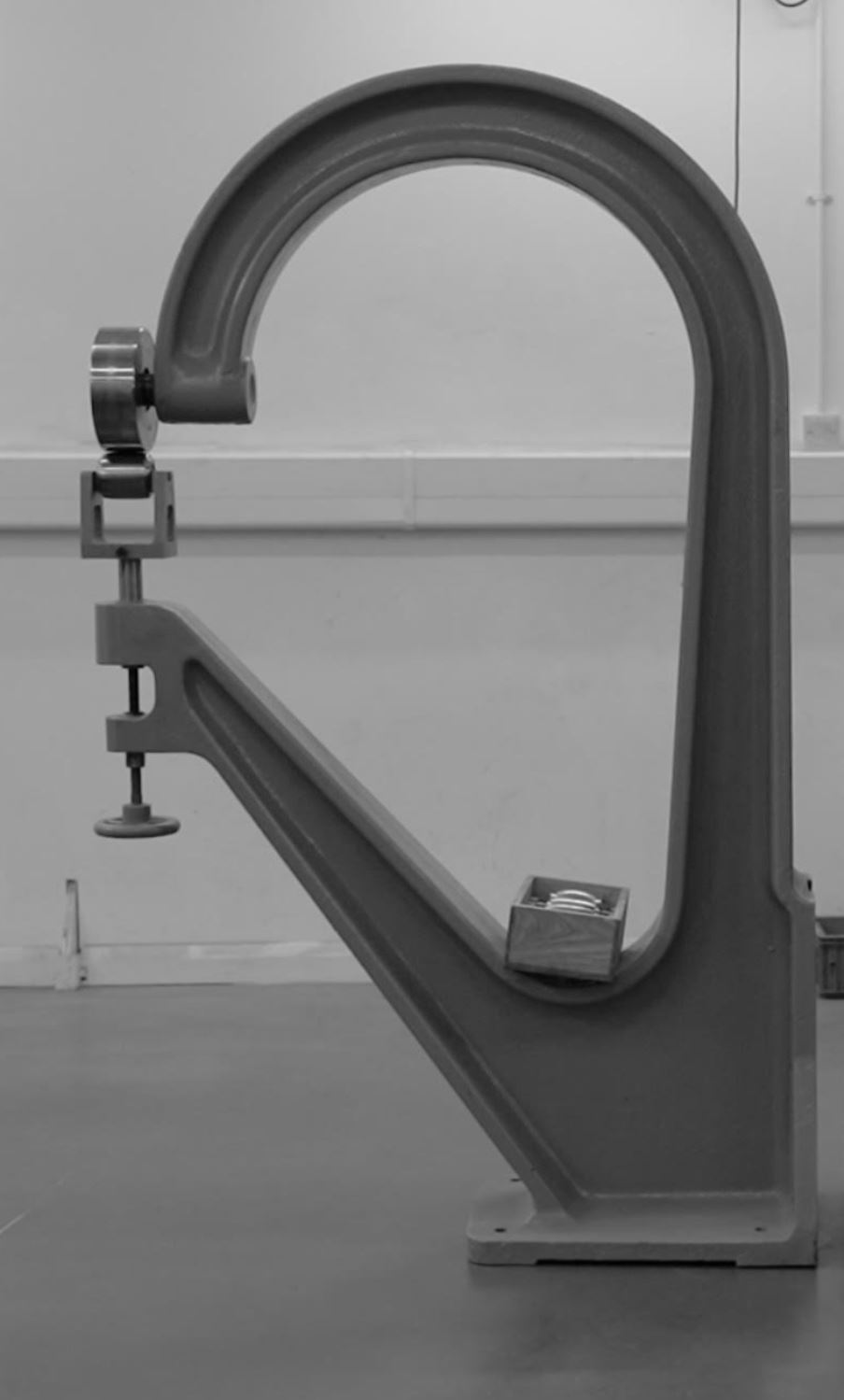
To form sheet metal into complex curves such as those needed to create the wheel fenders some specialised tooling is required.
Wheeling Machine / English Wheel – The sheet metal is passed between the anvil wheel and the rolling wheel. This process stretches the material and causes it to become thinner. As the material stretches, it forms a convex surface over the anvil wheel.
Below is an image of a Ranalah wheeling machine, which was nicknamed the spitfire wheel as it was extensively used in making of the Spitfire, the company Ranalah was relaunched in 2021 by Dominic Chinea of The Repair Shop.
Along with my friend Brian Hembrow who has been assisting me with some of the engineering parts of this project we decided to make a wheeling machine rather than purchasing one. Below are some images of the wheeling machine during manufacture. The last image shows a shrinker / stretcher tool which is also being made to assist with the metal forming tasks.
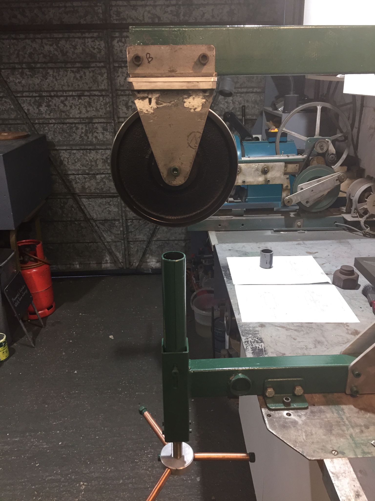
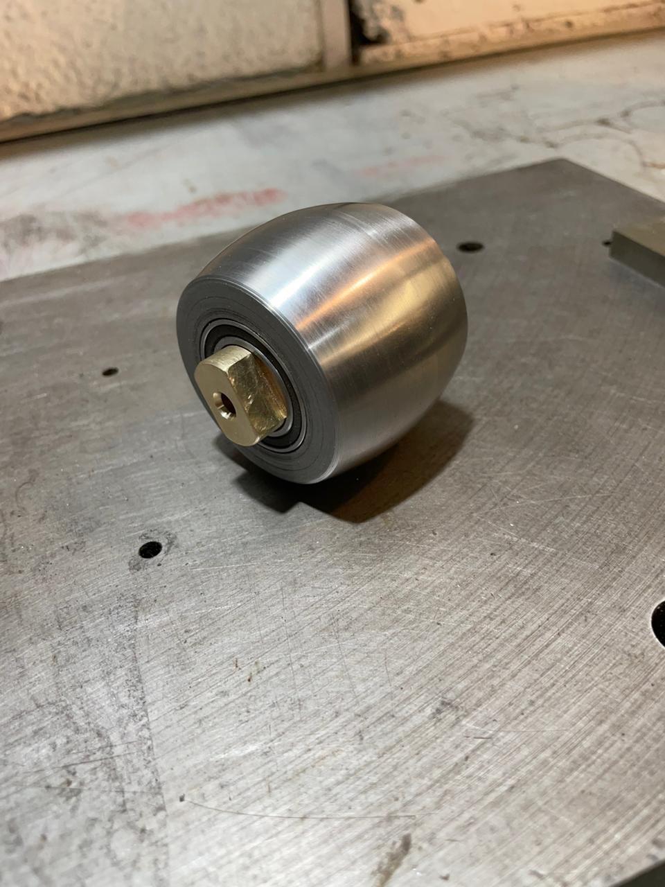
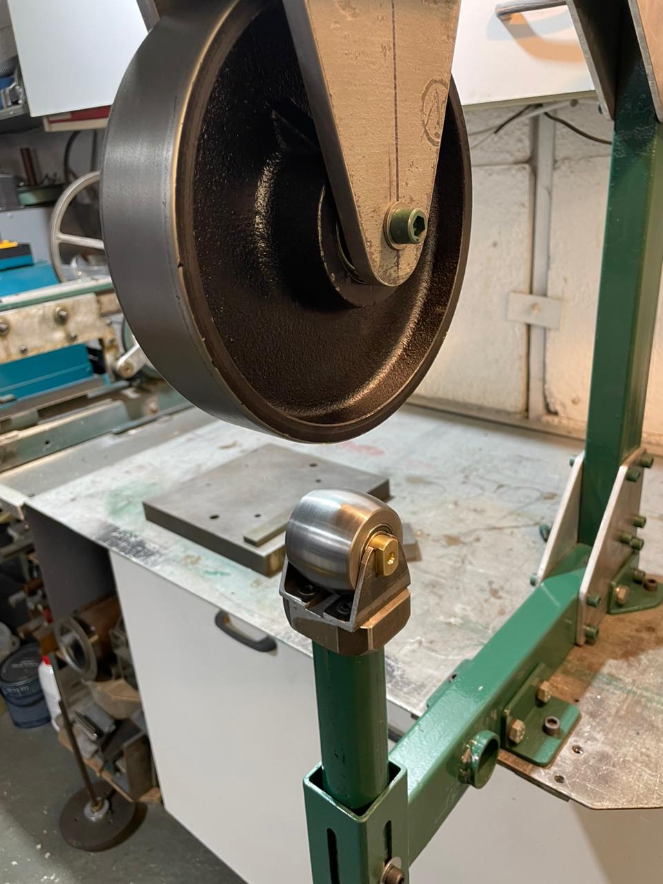
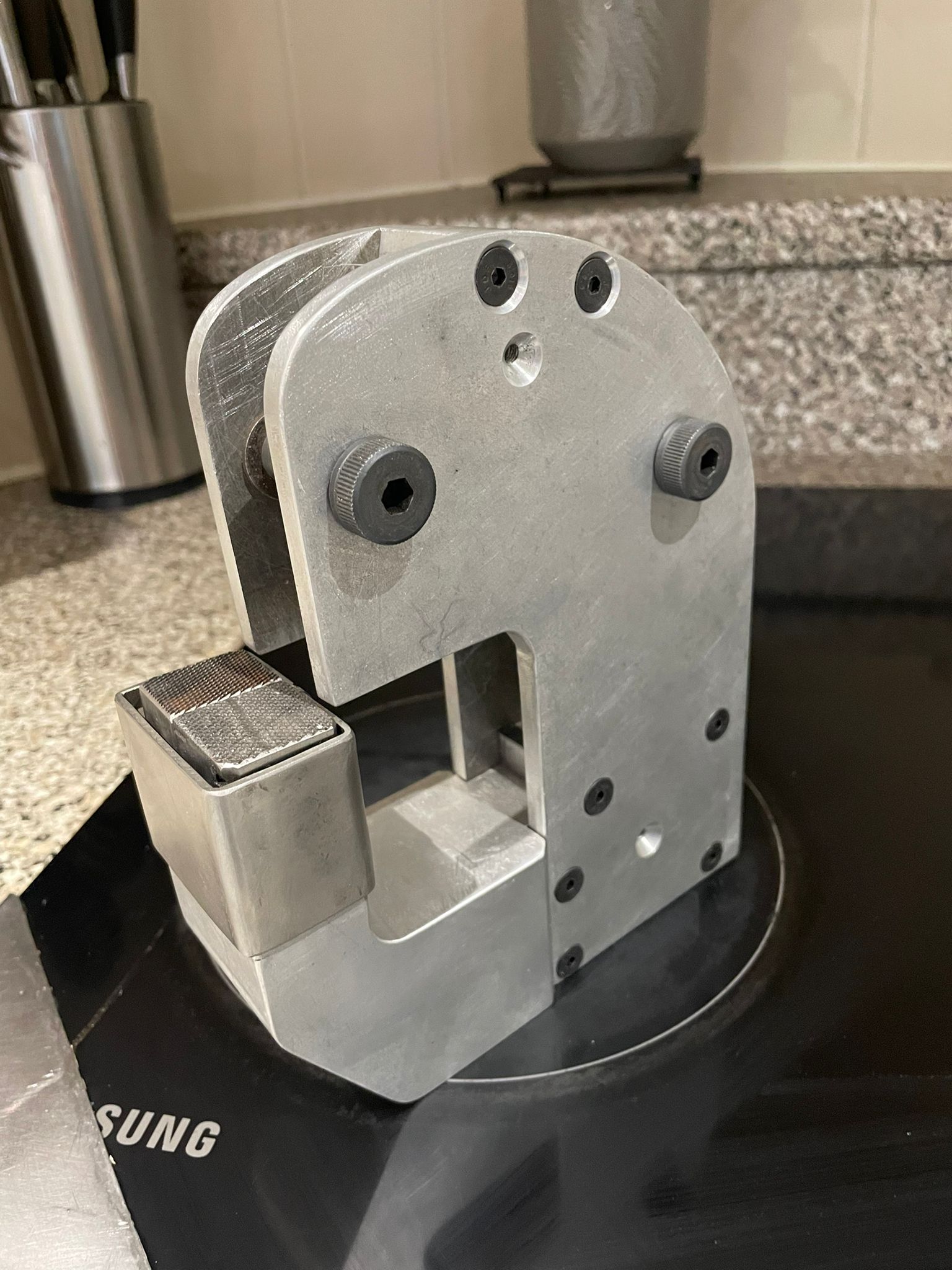
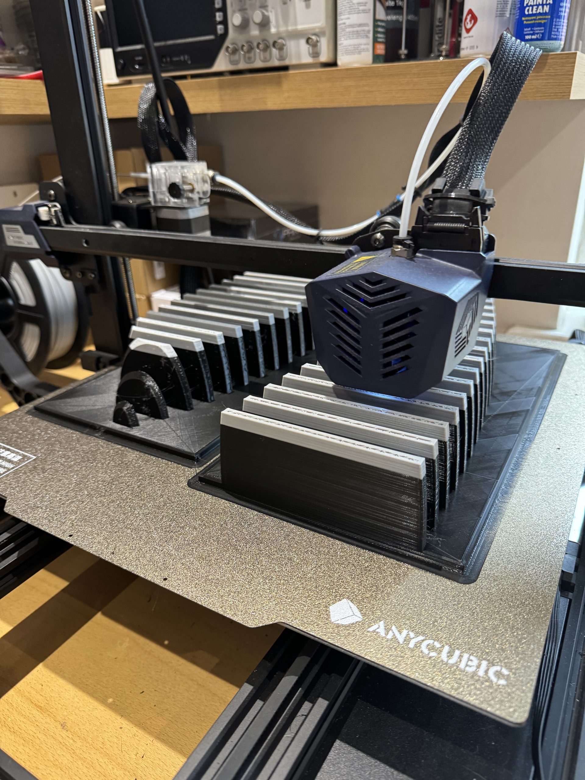
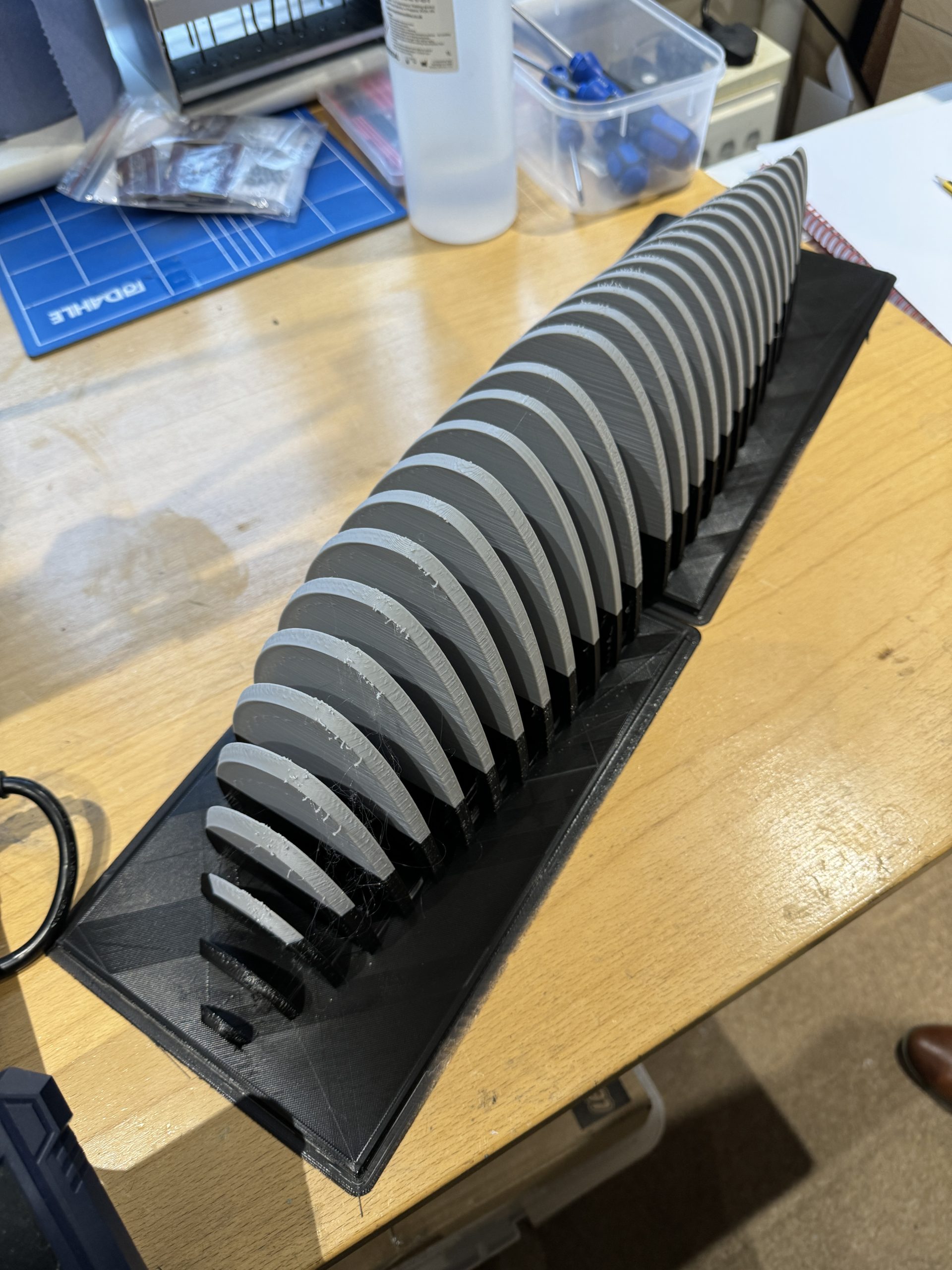
The 3D bucks were first designed in Fusion 360, two bucks will be created for each of the fenders, eight bucks in total. The bucks for each fender would have one with the main shape and then another including the body profile.
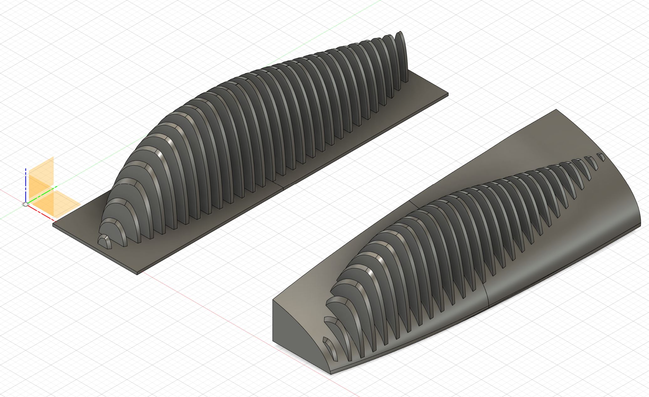
Below is the first of bucks during printing and after printing on 3D printer. The two colours have no significance, I was simply using up some PLA filament that I had available.
